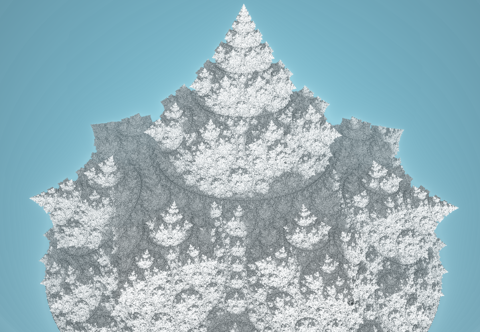
Sunday, June 4, 2023

Inversion Tree

 A while ago I wrote about three variable-dimension surfaces, which included a sphere inversion-based surface. The idea is to use a disk packing and then convert each disk into a spherical bulge and repeat. 

At the time I only knew about the Apollonian Gasket sort of disk packings, and these have the problem that finite sized disks touch each other, so if you keep adding bulges then the surface will self-intersect. For this reason I chose a type of packing where I could toggle the direction to prevent intersections. But the result is not a tree for this reason. 

If we instead make use of Kleinian packings such as the G8 packing, then finite disks don't butt up against each other, and the disk radii drop relatively uniformly with distance to the disk edge. It is therefore possible convert them all into spherical bulges without self-intersection. 

The method follows that in the Kajino paper but with a bigger family of disk packings. Here the G8 group example is used, like in my recent post:

The left image is the limit set and the right shows the three symmetries used to generated it. These are defined by the three green lines (exactly as used previously) and the purple L4 line. To see if a point is in the set, repeatedly:
1. reflect around the two straight lines until the point is within that wedge
2. if the point is inside the l2 circle then invert around that circle
3. if the point is inside the l4 circle then revert around that circle
4. if the point is outside the centred green circle then colour white and exit
colour black if iterations ended

Notice that these transformations never make the space (close clusters of points) smaller, so this is a form of escape-time fractal. If we use the l2,l4 labels for the two circle radii and the letter L for the distance of l4's centre from the origin then:

- l2 = sec(pi/o1) / sqrt(cosec^2(pi/n) - sec^2(pi/o1))

- L = sqrt(1+l2^2)

- l4 = L sin(pi/o2 - asin(l2 sin(pi-pi/o2)/L)/sin(pi - pi/o2)

Where n is the number of child disks to the central one, and o1 and and o2 are two different order numbers, in particular, o1 is the number of hyperbolic tesselation regular polygons that meet at each vertex.

While all produce types of Kleinian group, it so happens that the types that I want (no bald spots, no black disks) happen when o2=3 and when o1 is the smallest value that is hyperbolic. For example if n=6 then three regular hexagons meeting at each vertex is a Euclidean tiling, so you need o1=4. For n from 4 up to 9 the values of o1 are therefore 5,4,4,3,3,3 respectively. The resulting tilings are shown in reading order here:


Hopefully you can see the number of children around the central disk grows from 4 up to 9, and that no two (finite sized) disks ever butt up against each other. You may also notice that the central disk size doesn't grow in a simple way with n, that is because o1 is changing, only remaining constant on the bottom row.

In order to render this as a tree of bulging disks we need to develop an approximate distance estimator. The method I use per iteration is as follows:

1. if the point is outside some spherical region above the disk then return the distance to a slightly smaller spherical region (scaled by the running scale). This is heuristic so takes some tuning.

2. apply the above escape-time transformations for limit set as a horizontal unit disk, but make sure that sphere inversions are 3D. 

3. if the point is within a sphere that encompasses the central disk, then apply a conformal transformation that bends the desired spherical bulge back to a flat disk, and scales it back to the unit disk.

if iterations run out then return the distance to the flat disk (scaled by the running scale).


This 'desired spherical bulge' is specified by a bend angle parameter which describes how much the bulge lifts up relative to being flat. We therefore are left with a tree family defined by two parameters: n and bendAngle.

Here is n=8 at bendAngle 0.3 up to 1.3 in steps of 0.2:


And here is bendAngle 1 for values of n from 4 up to 9, in reading order:


As with the 2D images above, there isn't a simple progression of the shape because o1 is changing, but the shape is largely governed by how large the central disk is.

As you can see, it not only generates a tree, but for large enough bendAngle it generates a tree-sponge when the branches touch, and then a sponge for higher bendAngle. It almost certainly then generates a foam structure at larger bend angles, but the distance estimator gets challenging to develop at these large angles.

We can look at just the inner disk shape, which is equivalent to applying the curve on the outer disk, here are some examples:
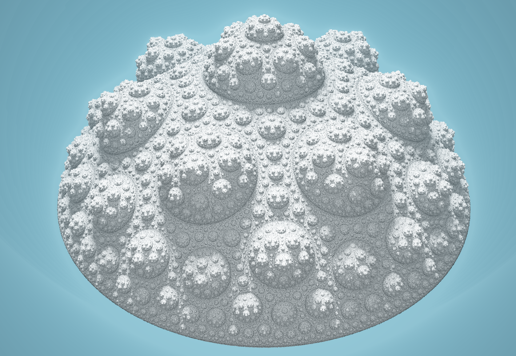
n=7
n=5
n=8
n=4
n=8
n=6
n=6
n=8

For the large bend angles producing a sponge, you need to tweak the bend angle to get a Kleinian group (circles are circles) rather than a pseudo-Kleinian (partial-circles), the above image has bend angle 1.26 to achieve this.


Tuesday, May 30, 2023

Sphere Cluster

We can generate 3D clusters in a similar way to the previous post, but using a hyperbolic regular polyhedron tiling instead of a hyperbolic regular polygon tiling. We can continue to use this 2D diagram as a guide:

We define the outer green circle as radius 1, and the offset green circle l2 has its centre at a distance L=sqrt(1+R^2) where R is the solution to:

 R/theta = sqrt(1+R^2)/sin(pi/2 + pi/m)

where theta is the angle from the polyhedron centre to the nearest face edge and m is the number of polyhedrons that meet at each edge. There are two good polyhedrons to use here, the dodecahedron and the icosahedron, their values and resulting formula are: 

 Dodecahedron: 

  • theta = atan2(phi+2, 2phi + 2 + 1/phi)
  • m      = 4
  • R      = sqrt(2)/sqrt(-2 + cosec^2(theta))
Icosahedron:
  • theta = atan2(phi, 1+2phi)
  • m      = 3
  • R      = 2/sqrt(-4 + cosec^2(theta))
Where phi is the golden ratio, and the inner red circle has radius r=L-R.

To render in 3D we want to do something better than just an inside-outside test, we want to approximate the distance to the nearest surface. It goes roughly like this... invert each query point p around the red radius r sphere then:

  1. rotate the point to a be radially in one single polyhedron face*
  2. if it is inside l2 you invert it around l2
  3. if its magnitude is less than rk (plus a skin width) then divide by rk and then invert around l4 = sqrt(r), sending the red sphere to the outer green unit sphere
  4. once you are out of iterations return the distance to the centre sphere rk, multiplier by a scale factor that is initialised to 1 and grows in proportion to all transformations of p in the above steps
* this is a bit harder in 3D than 2D. The simplest I can think of is to fold the point around the planes defined by the origin and each edge of the chosen face. For the dodecahedron the chosen face has vertices in order: (1/phi,0,phi), (1,-1,1), (phi, -1/phi,0), (phi,1/phi,0), (1,1,1). For the icosahedron the three vertices are (0,1,phi), (0,1,-phi), (phi,0,1). The planes can be generated using the cross product of adjacent vertices. I found that for the dodecahedron you just need to fold around each edge twice to guarantee the point ends up radially in the specified face, and for the icosahedron you need to do it three times. 

The direction to the l2 sphere centre is then the direction to this face centre, which is the mean of the above vertices.

The resulting approximate signed distance function to the shape's surface is sampled in Fragmentarium in order to generate a rendering of the shape with lighting and shadows. 

Here is the result for the dodecahedral cluster, with k values from 0.7 up to 1:


Here against a black background, a close up of k=0.7:
and k=0.8:
and k=0.1:

For the icosahedral cluster, here are k values of 0.7 up to 1:


Both the decahedral and the icosahedral become cluster-sponges at k=1, and are very spikey and visually less rough. We can make the shape less spikey at higher k by alternating between the dodecahedral and the icosahedral clusters. Since they are duals of each other, we should expect that to do the opposite of lining up subclusters. 

There are two versions depending on which shape you start with. Here starting with the dodecahedral with k from 0.8 up to 1:


a close up at k=1:

Here we start with the icosahedral shape, k = 0.7 to 1:


It is a bit hard to render this fractal for k>=1, but if you replace the final distance calculation with a slightly smaller sphere distance then it makes no difference to the limit set, and avoids some rendering artifacts for k>1, which is when the shape changes from a cluster to a sponge.

So here is the icosahedral fractal for k=1 and k=1.3:


and the dodecahedral from k=1 up to k=1.6:


If you toggle between icosahedral and dodecahedral, it is a bit more organic looking:

k=1.1 starting dodecahedral:
k=1.2


Starting icosahedral, k=1.1:
k=1.16
k=1.17