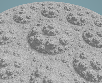
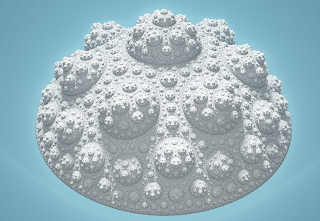
We can generate 3D clusters in a similar way to the previous post, but using a hyperbolic regular polyhedron tiling instead of a hyperbolic regular polygon tiling. We can continue to use this 2D diagram as a guide:
We define the outer green circle as radius 1, and the offset green circle l2 has its centre at a distance L=sqrt(1+R^2) where R is the solution to:
R/theta = sqrt(1+R^2)/sin(pi/2 + pi/m)
where theta is the angle from the polyhedron centre to the nearest face edge and m is the number of polyhedrons that meet at each edge. There are two good polyhedrons to use here, the dodecahedron and the icosahedron, their values and resulting formula are:
Dodecahedron:
- theta = atan2(phi+2, 2phi + 2 + 1/phi)
- m = 4
- R = sqrt(2)/sqrt(-2 + cosec^2(theta))
Icosahedron:
- theta = atan2(phi, 1+2phi)
- m = 3
- R = 2/sqrt(-4 + cosec^2(theta))
Where phi is the golden ratio, and the inner red circle has radius r=L-R.
To render in 3D we want to do something better than just an inside-outside test, we want to approximate the distance to the nearest surface. It goes roughly like this... invert each query point p around the red radius r sphere then:
- rotate the point to a be radially in one single polyhedron face*
- if it is inside l2 you invert it around l2
- if its magnitude is less than rk (plus a skin width) then divide by rk and then invert around l4 = sqrt(r), sending the red sphere to the outer green unit sphere
- once you are out of iterations return the distance to the centre sphere rk, multiplier by a scale factor that is initialised to 1 and grows in proportion to all transformations of p in the above steps
* this is a bit harder in 3D than 2D. The simplest I can think of is to fold the point around the planes defined by the origin and each edge of the chosen face. For the dodecahedron the chosen face has vertices in order: (1/phi,0,phi), (1,-1,1), (phi, -1/phi,0), (phi,1/phi,0), (1,1,1). For the icosahedron the three vertices are (0,1,phi), (0,1,-phi), (phi,0,1). The planes can be generated using the cross product of adjacent vertices. I found that for the dodecahedron you just need to fold around each edge twice to guarantee the point ends up radially in the specified face, and for the icosahedron you need to do it three times.
The direction to the l2 sphere centre is then the direction to this face centre, which is the mean of the above vertices.
The resulting approximate signed distance function to the shape's surface is sampled in Fragmentarium in order to generate a rendering of the shape with lighting and shadows.
Here is the result for the dodecahedral cluster, with k values from 0.7 up to 1:
Here against a black background, a close up of k=0.7:
and k=0.8:
and k=0.1:
For the icosahedral cluster, here are k values of 0.7 up to 1:

Both the decahedral and the icosahedral become cluster-sponges at k=1, and are very spikey and visually less rough. We can make the shape less spikey at higher k by alternating between the dodecahedral and the icosahedral clusters. Since they are duals of each other, we should expect that to do the opposite of lining up subclusters.
There are two versions depending on which shape you start with. Here starting with the dodecahedral with k from 0.8 up to 1:
a close up at k=1:
Here we start with the icosahedral shape, k = 0.7 to 1:
It is a bit hard to render this fractal for k>=1, but if you replace the final distance calculation with a slightly smaller sphere distance then it makes no difference to the limit set, and avoids some rendering artifacts for k>1, which is when the shape changes from a cluster to a sponge.
So here is the icosahedral fractal for k=1 and k=1.3:
and the dodecahedral from k=1 up to k=1.6:
If you toggle between icosahedral and dodecahedral, it is a bit more organic looking:
k=1.1 starting dodecahedral:
Starting icosahedral, k=1.1:
k=1.16
k=1.17


